Fig. 4
Since the main purpose of this study is to find the possibility of developing an engine that uses only environmentally friendly energy sources (pure energy sources), it is natural to apply, as an external force, the force of fields of permanent magnets. However, there is no possibility to influence by means of magnets on the metal balls if they are within the disk or near its surface, as it is shown in Fig. 1. The disk should also be made of metal to provide the necessary durability, i.e. it can affect distribution of the magnetic field. Therefore it is natural solution - to remove the loads from the disk, and equip them with permanent magnets. At the same time, these loads should be mechanically linked with the disk in such a way that impact force of gravity on the centres of gravity of such loads would be transferred to the disk at the same points, which are shown in Fig. 2 as the centers of mass of the spherical loads. It is also necessary provide an opportunity of the corresponding displacement of the loads under the influence of the gravitational field of the Earth in order to use of the kinetic energy of the falling of the loads.
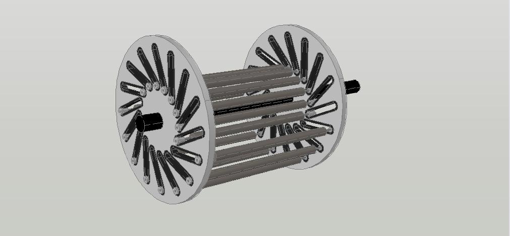
In Fig. 4 is shown the variant of design the rotor of motor, corresponding to these requirements.
Here upon the rotor shaft are rigidly fixed two identical disks whose axes coincide with the axis of rotation of the rotor. In the bodies of the disks, instead of closed tubes, as it was shown in Fig. 1, there are slotted inclined ways, closed at their ends. Work profile of these ways may resemble the external profile of the railway tracks. Loads are located in the space between the disks. Form of the loads - cylindrical. At the both ends of these loads there are the wheels, thanks to which the loads can move along the inclined paths. The inclined paths allow the arising of unequal lever arms of rotation when shifting along them the movable loads.
In the structure, which is shown in Fig. 4, as yet magnets are absent. However, this structure allows the use of loads which are cylindrical in shape and have a considerable length. The loads of cylindrical shape can have a mass many times as large versus the mass of the loads of spherical shape, used in the constructions corresponding to Fig. 1. Consequently, the torque created by each cylindrical load can be many times greater than the torque generated by the spherical load.
Since in accordance with Newton's Law of Universal Gravitation the force of gravitational impact is directly proportional to the mass of a physical object, any designer of the engine, who wants to harness the energy of the gravitational field, must endeavor to provide the ability of using the movable loads with as much as possible mass. In the proposed design of the motor rotor the sizes of the movable loads, and hence the mass each of them, limited only by the size of the space between the two disks, which can be made large enough due to the possibility of increasing the diameter of disks and the distance between them.
In the construction corresponding to Fig. 4 the weight of each load is divided equally between the two disks, and so it impacts on them through the points analogous to those which are shown in Fig. 2 as the centers of gravity of the moving spherical loads. Therefore, we can analyze the system of two disks, as if it were one disk which was placed in the middle between them, to which can be applied the results of the calculation in general form of the net torque device analogous to "Indian wheel", adduced in Appendix 1 – Calculation in general form the net torque of the device, similar to "Indian wheel". Hence also in this device, at the absence impact of the external force, additional with respect to the force of gravity, the net torque is equal zero. And if there is only gravitational impact, such a device is characterized by a multitude of possible states of stable equilibrium, the number of which is equal the number of inclined paths for movable loads.
But in the construction shown in Fig. 4, in contrast to the structure corresponding to Figures 1 and 2, the movable loads are located outside the disk - in the space between a pair of disks. With such arrangement of the movable loads they can be equipped with permanent magnets. It has become possible the placement of stationary permanent magnets in close proximity to the trajectory of motion of the loads. And, what is the most importantly, it has become possible the placement of stationary magnets in the space where they can counteract the gravitational impact on the movable loads due to the phenomenon of levitation magnets, that is, in the space corresponding the sector A8 – O – A11 (Fig. 2). As mentioned above, the counteraction to the gravitational impact in this sector of rotation must provide the creation of the initial torque on the shaft of motor. Formation the additional rotatory exertion may be possible by the corresponding placement of stationary permanent magnets into the other sectors of rotation.
Thus, in such structure rotor of motor are created the favorable conditions for providing the possibility interaction of the fields of movable and stationary magnets, capable not only to lead out the system from the state of stable equilibrium, but also ensure the long-term and efficient engine operation due to sharing of the kinetic energy of gravitation and the energy of interaction of the permanent magnets.
This page was last modified on 18 September 2014